
Machine Vision
Camera Calibration
A 3D camera, mounted on the excavator arm, is used to take images of the dirt and dump truck. This camera must be calibrated using a checkerboard calibration board. The data gathered from the calibration images allows the camera to remove distortion from images.

2D image from each lense
3D Mapping
In order to get a 3D mapping of the area captures in the camera, the image distortion is removed and then a point to point comparison of the two images are made. This creates a disparity map, which correlates to distance and location of the pixel with respect to the camera. This data can be used to find the x, y, and z location of any point in the image.

Point to point comparison
Object Recognition
After finding the x, y, and z location of the image pixels, it is necessary to find the pixel of interest. In this example, it is the center of the truck bed. Note that the same method is used to find the center of the dirt pile. Using one of the 2D images, color filtering is used to and then the image is turned into a binary image. This filters out the bed of the truck such that the center of the truck bed can be found.

Binary truck image
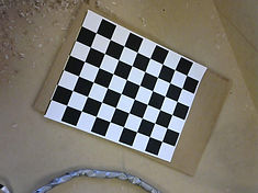
Calibration board
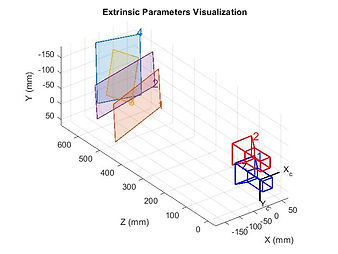
Visualization of camera parameters

Disparity map
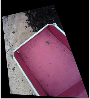
Identified centroid of truck

Identified centroid of dirt